- Products & Capabilities

- About
- Resources
How to Test a Diode in A Circuit


Testing diodes with a multimeter is crucial for ensuring reliable performance and preventing failures in electronic appliances by directing current flow effectively.
In the intricate world of electronics, diodes are small but essential components that play a vital role in determining the efficiency and performance of most household products. It is imperative to ensure that diodes function correctly in order to enjoy the consistent performance of appliances we utilize daily, such as microwaves, refrigerators, air conditioners, and washing machines. A malfunctioning diode can lead to inconvenient and disruptive failures, like an air conditioner that fails during a sweltering summer or a non-functional microwave when you’re trying to prepare a meal. Understanding how to test diodes in a circuit board is paramount for preventing these issues and maintaining the dependability of your electronic devices.
Essentially, diodes are semiconductor devices that allow current to flow in only one direction, serving as one-way valves in circuits. This is critical in preventing damage due to bidirectional current flow, which would annihilate the function of an electronic device. By controlling the directionality of current flow, diodes protect circuits and facilitate stable operation, and hence their function should never be compromised.
What is a Diode Test?
A diode test is a testing method for establishing whether a diode is functional. The test determines whether the diode is conducting electricity in one direction (forward bias) and not in the other direction (reverse bias). The determination is normally conducted by using either an analog or digital multimeter that offers in-circuit and out-of-circuit testing and definitive determination of whether the diode is in good condition.
Failure Modes of Diodes in Circuits
Diodes can fail due to numerous reasons, and understanding these can assist in diagnosis:
Open Circuits: A broken path in the circuit that prevents current flow.
Short Circuits: An action that connects the two circuit points, allowing current to bypass the diode.
Odd Voltage Regulation: Diodes losing their functionality to supply constant voltage across them.
Unbalanced Output: Output variations approved by inconsistent performance.
Zero Supply Voltage: No voltage applied rendering the diode useless.
Power Supply Surges: Voltage spikes stressing the diode beyond its limits into failure.
All of these types of failure can cause serious issues in the device, so testing and debugging are essential.
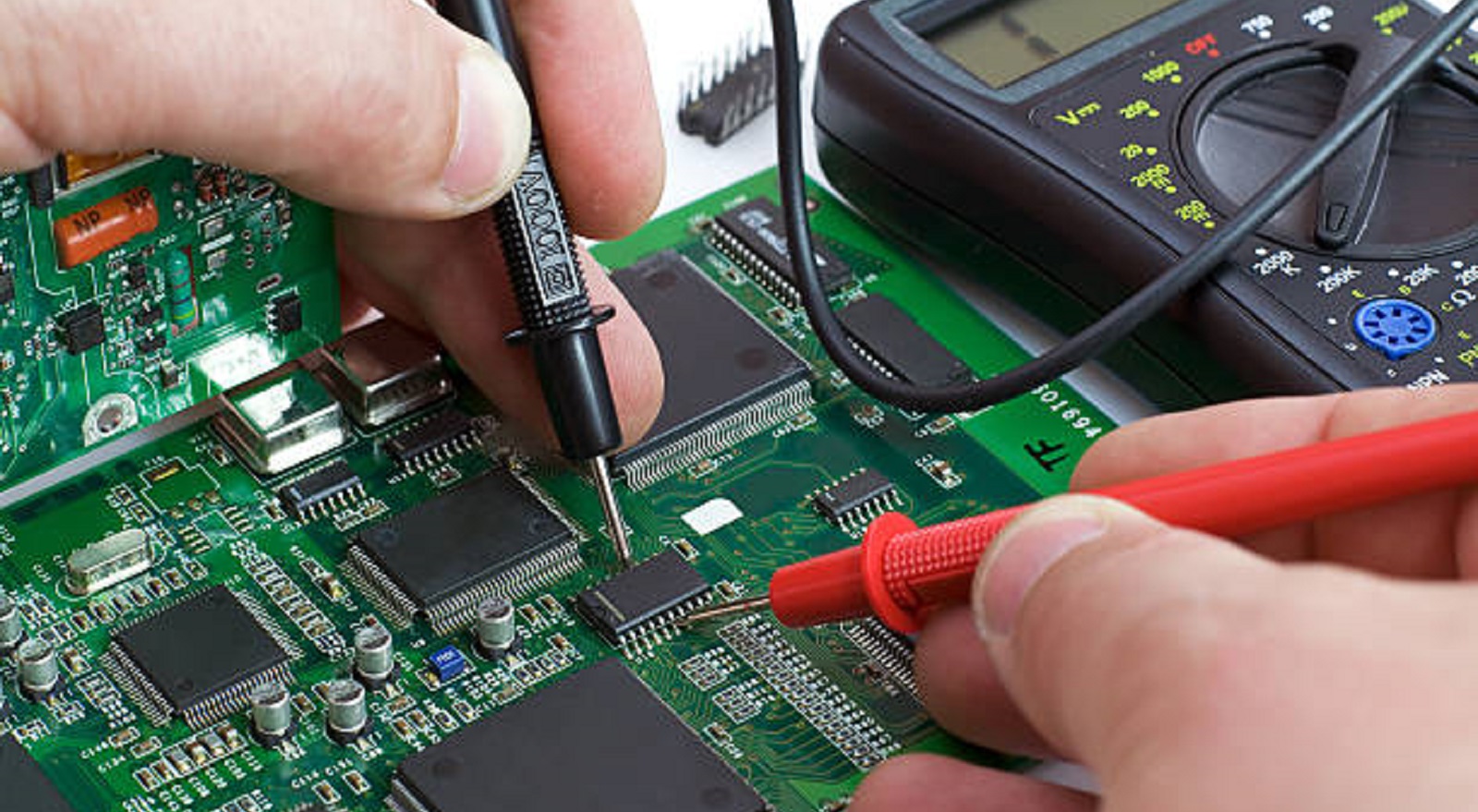
Testing Diodes with a Multimeter
Diode testing must be precise, diode operation known, and measurements taken with care written down. The following is a detailed look at testing diodes using different types of multimeters.
Using an Analog Multimeter
The analog multimeter provides a simple but useful way of diode testing by measuring resistance:
Set the Resistance Mode: Begin by placing the analog multimeter on a low resistance setting.
Connect the Probes: Connect the red probe to the anode of the diode and black probe to the cathode to test in forward bias.
Reverse the Probes for Reverse Bias: Reverse the probes will test the reverse bias state. A high resistance value, generally indicated as 'OL' (open loop), confirms the blocking action of the diode.
Interpret Results: A functioning diode will show different resistance readings for forward and reverse biases. Same or low resistance in both cases shows a short, whereas zero reading in either case may show an open diode.
Using a Digital Multimeter
Digital multimeters offer additional test modes, such as a dedicated diode mode, which simplifies the process:
Switch to Diode Mode: Set your digital multimeter to the diode function, symbolized by a diode icon.
Establish Forward Bias: Connect the red lead to the anode and the black to the cathode. The meter will register a voltage drop, usually 0.6V to 0.7V for silicon diodes.
Test Reverse Bias: Reverse the leads (black to anode, red to cathode). The multimeter will now read 'OL' or high resistance indicating no conductivity.
Evaluate Measurements: A healthy operation is indicated by a clear forward voltage and open circuit reverse.
Testing Diodes Without Using a Multimeter
Less common but possible without a multimeter is diode testing using a continuity circuit or component tester:
Continuity Circuit Testing: An LED will blink in forward bias, attesting to conductivity. Lack of blink in reverse bias demonstrates the diode's blocking function.
Component Tester: Confirms diode health by checking for a forward voltage reading (VF), ensuring it is within expected tolerances.
Diodes are not optional parts but play a crucial role in the trouble-free functioning of consumer electronics. Diode failure, if not detected, can cause significant malfunction, and thus, it is essential to conduct testing and maintenance regularly. Proper testing, whether with a multimeter or otherwise, will ascertain that any fault can be easily detected and taken care of, ensuring the uninterrupted functioning of electronic equipment.
At PCBX, we understand the significance of diodes in circuit board design and operation. We hope this comprehensive guide simplifies testing for you, enabling efficient diagnostics and maintenance of your electronics. For further assistance or professional PCB services, contact PCBX, where our commitment is to meet all your electronic needs with precision and expertise.
Hot Tags:

Contact us

If you can't find what you're looking for, please contact us.
Article
Current limit control circuits safeguard electronics by regulating excess current, ensuring device safety and reliability across various applications and industries.
 2025/01/20
Diodes, key in PCB design, ensure unidirectional current. Understanding anode/cathode roles boosts circuit reliability and efficiency in electronics.
2025/01/10
Diodes control current flow in circuits. Regular testing using tools like multimeters ensures performance, reliability, and protection of electronic components.
2024/12/03