- Products & Capabilities

- About
- Resources
What is Reliability Test in PCB?


PCBs require rigorous reliability testing to ensure long-term durability, performance across industries, and standards compliance, minimizing failure risks.
In our technology-driven age, Printed Circuit Boards (PCBs) form essential components of nearly all electronic devices, from consumer durables to aerospace and medical life-critical systems. Their reliability is central to maintaining performance levels in numerous industries, including the automotive and industrial sectors. With such stakes, PCB reliability testing is critically important to determine that they can meet long-term service expectations. This article explains the need for PCB reliability testing, discusses common failure modes, summarizes key test methodologies, and emphasizes the need for industry standards.
The Importance of PCB Reliability Testing
Reliability testing is a vital part of the PCB manufacturing process, assuring stakeholders that the product will perform as intended under specified conditions for its entire life. Key reasons for reliability testing include:
Risk Mitigation: Avoidance of design and manufacturing flaws by early detection reduces expenditures on recalls and field failure, protecting the manufacturer's reputation along with consumer safety.
Process Validation: Confirms that each phase in manufacturing consistently yields high-quality products to specified guidelines.
Material Qualification: Ensures substrates, bonding, and coatings possess the capability to withstand environmental stresses over a period of time.
Design Verification: Validates that the layout and components possess the capability to endure operational stress without failure.
Standards Compliance: Compliance with standards such as IPC, JEDEC, and MIL-STD is crucial for consumer acceptance and confidence in the marketplace.
Continuous Improvement: Test data enables repetitive design protocol refinement, quality control procedures, and manufacturing processes.
While testing the failures, manufacturers can detect and rectify the weaknesses and thus prevent future in-field failures.
Common PCB Failure Mechanisms
Understanding the likely failure modes is critical to designing good reliability tests. Common PCB failures are:
Electrical Shorts: Caused by conductive trash or inadequate spacing, promoting dendritic growth and short circuits between conductors.
Open Conductors: Can be induced by thermal cycling or mechanical shock, leading to copper trace cracks or solder joint fractures.
Intermittent Contacts: Vibration can cause temporary contact losses, with environmental conditions producing contact resistance through fretting corrosion.
Dielectric Breakdown: Moisture and exposure to high voltage can potentially cause electrical arcing and dielectric failure.
Cracking and Fracture: Differences in thermal expansion or mechanical shock might result in cracking of parts.
Corrosion and Dendrites: Environmental exposure might lead to metal migration and electrical leakage.
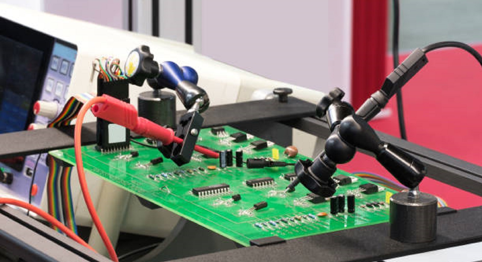
Key Methods for PCB Reliability Testing
Reliability testing would mean simulation of the stressors that PCBs will experience in real-world usage, allowing accelerated failure condition predictions. Primary test methods include:
Temperature Cycling: Evaluates thermal stress by subjecting PCBs to temperature extremes, typically -55°C to 125°C.
Power Cycling: Involves several on/off power cycles to assess thermal transient stresses, searching for defects like intermittent contact or component failure.
Vibration Testing: Exposed boards to different vibration profiles (commonly 10-2000Hz) to identify weaknesses in solder joints and susceptibility to metal fatigue.
Mechanical Shock Testing: Severe impacts are administered to examine the integrity of boards, identifying potential breaks or weak points.
Humidity/Temperature/Bias Testing (HTB): Depicts conditions promoting electrical arcing and corrosion, testing for resistance against humidity, temperature, and electrical stress.
Mixed Flowing Gas (MFG): Accelerates surface corrosion and metal migration by exposing powered boards to reactive gases.
These methods are tailored to expose weaknesses, providing feedback for product improvement.
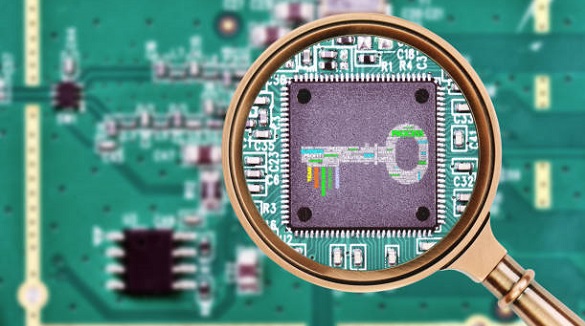
Interpreting Test Results
Testing results provide required data for PCB development refinement:
Pass/Fail Data: Determines whether boards remain functional after testing, critical to meet qualification requirements.
Parametric Drift: Tracks changes in electrical parameters like capacitance and resistance, which can signal degradation issues.
Failure Analysis: Uses methods like Scanning Electron Microscopy (SEM) to uncover underlying root causes of failure and guide corrective action.
Bathtub Curve Analysis: Graphs cumulative failures versus time, making failure rate analysis and determination of where design should be strengthened possible.
These are essential to ongoing design and production refinement, allowing product reliability and longevity.
Industry Standards for Reliability Qualification
Standards conformity is essential to ensure PCB reliability:
IPC Standards: Offer guidance on accelerated testing, e.g., IPC-SM-785 for solder attachments and IPC-9701 for high-frequency boards.
JEDEC Standards: JESD22 mandates comprehensive reliability test procedures for electronic components.
Telcordia GR Standards: Set network reliability assurance and electrostatic discharge tolerance.
MIL-STD Standards: Such as MIL-STD-202 and MIL-PRF-31032 specify stress testing and certification for high-reliability PCBs.
IEC Standards: IEC 60068 provides environmental testing methods for various conditions.
Compliance with the standards qualifies PCB performance, facilitating market entry and product quality assurance.
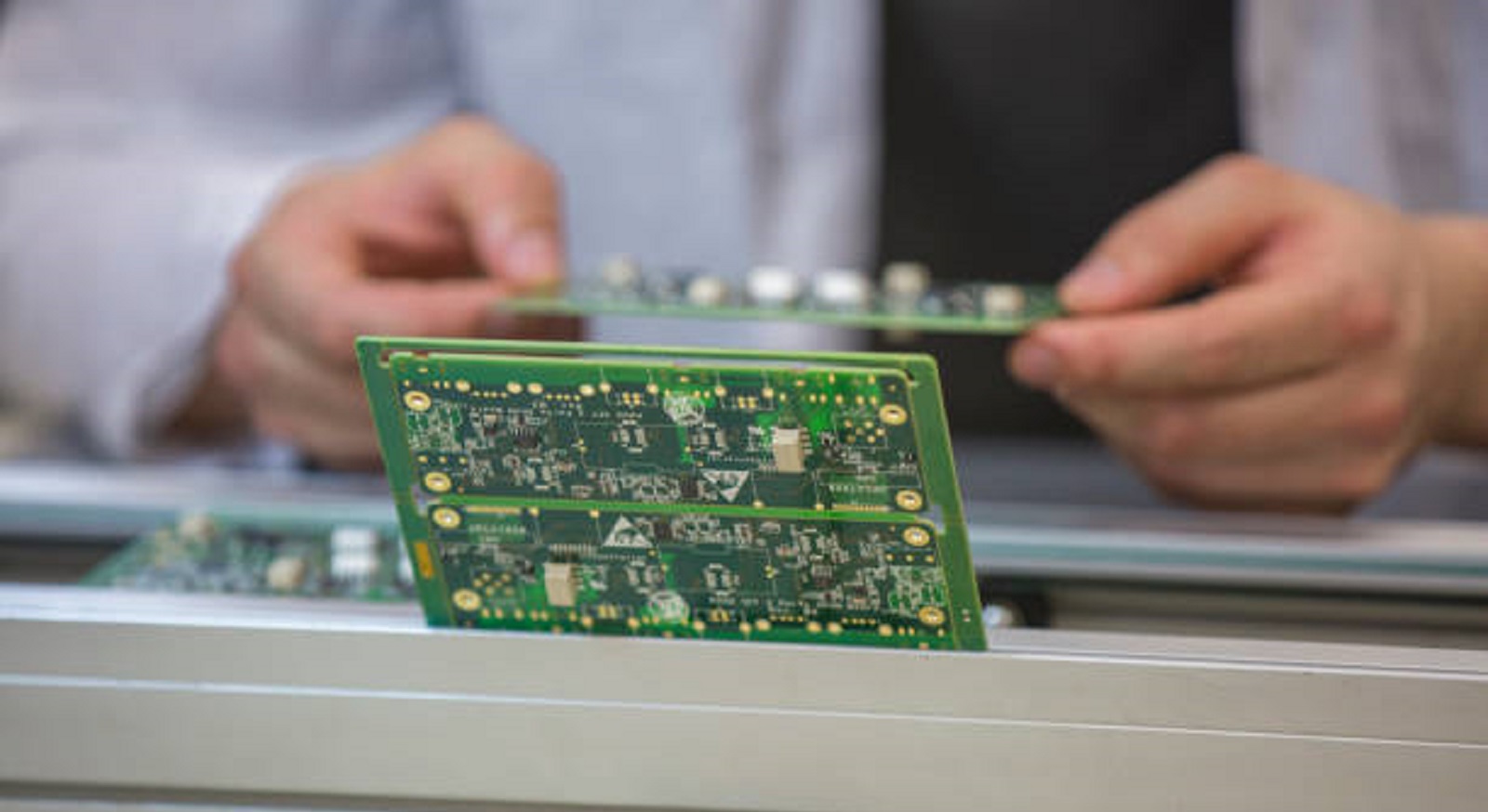
Integrating Reliability Testing in the PCB Development
Reliability testing at multiple phases of the PCB life enhances product lifespan:
Material and Component Testing: Confirms strength before mass-scale PCB designing.
Highly Accelerated Life Testing (HALT): Identifies failure points under extreme stress.
Failure Mode and Effects Analysis (FMEA): Predicts risk areas, guiding qualification procedures.
Prototype Testing: Supplies design optimization data by subjecting initial prototypes to stress tests.
Qualification and Continued Monitoring: Ensures compliance and continued quality during mass production scale-up.
In summary, high-quality PCB reliability testing is an essential step in equipping high-performance electronics with the capacity to meet modern demands. Including reliability testing in the production process enables manufacturers to minimize field failures significantly, offering long-lasting solutions for industrial applications of diverse nature. PCBX's commitment to rigorous reliability testing ensures that its products fulfill and exceed customer requirements, offering long-term solutions for mission-critical applications across diversified industries.
Hot Tags:

Contact us

If you can't find what you're looking for, please contact us.
Article
PCB test coupons simulate board elements for reliability checks, detecting early issues to ensure quality and performance before mass production.
 2024/10/31
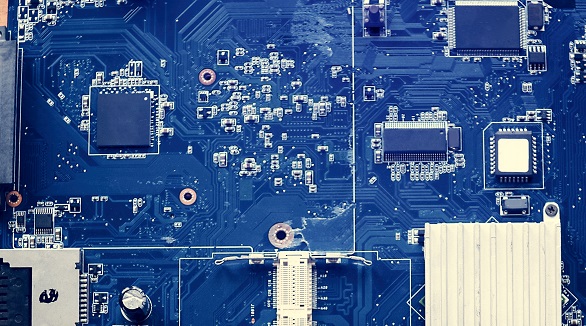
Functional testing verifies PCB functionality in simulated environments, enhancing quality and reliability, detecting faults, ensuring performance, and cost efficiency.
2024/10/25
PCB testing ensures quality and reliability by assessing key components like lamination, copper plating, and conductivity. Methods include ICT, FPT, Burn-in, and AOI. Testing reduces bugs, time, cost, and enhances safety.
2024/09/23