- Products & Capabilities

- About
- Resources
How to Choose the Right PCB Drill Bit


Choosing the right PCB drill bit: materials, sizing, types & tips for precise PCB drilling.
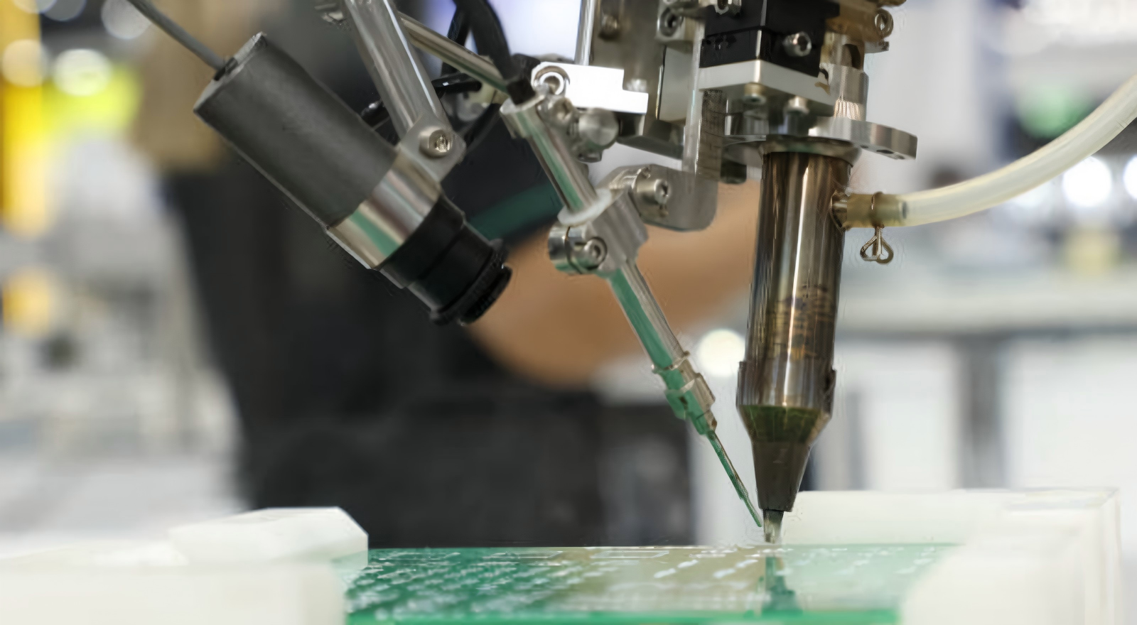
The precision drilling process is a critical stage in the PCB manufacturing process, and it can significantly affect the reliability of the board, the installation of components, and the manufacturing efficiency. Whether you’re working with standard FR-4 boards, multilayer circuits, or high-density microvias, selecting the right drill bit is critical to minimizing defects, reducing costs, and ensuring consistent results.
Why Choosing the Right Drill Bit Matters
One of the most time consuming and expensive processes during PCB production is drilling. A poorly designed drill bit can cause rough hole walls, burrs, resin smears, multilayer delamination, holes that are out of alignment or oval, frequent bit failure and delays in production. Whether it's for professional productions or hobbyist prototyping, choosing the right bit means cleaner holes, longer tool life, and reduced scrap rates.
Core Materials: Carbide vs. HSS
The hardness, wear life and suitability of the drill bit for PCB substrates depends on the base material of the drill bit, and there are two main considerations:
Solid Tungsten Carbide: The industry standard for professional use. It has excellent hardness, rigidity and heat resistance properties, which are suitable for the production of multilayer boards, microvias and abrasive FR-4. Excellent service life of 500 to 1000+ holes per bit to keep their sharpness in high speed CNC drilling and reduce deflection to obtain accurate holes. It is suitable for mass production, especially and precision applications.
High-Speed Steel (HSS): A cost effective choice for light duty applications. It is not as hard as others, wears out rapidly on fiberglass (only 50-100 holes in FR-4) and tends to heat up and chip. Low volume single-layer boards and non-abrasive materials – only for hobbyist prototyping.
Drill Bit Sizing, Types, and Applications
When using components, vias, and mounting, make sure that your drill bit fits the hole size and performs the proper function, including for plated through-holes (PTH), because the hole size varies depending on the thickness of copper plating.
Sizing Guide
Microvias (HDI/multilayer boards): 0.1 mm – 0.3 mm
Special vias & holes for components: 0.6 mm – 1.5 mm
The mounting & connector holes: 2.0 mm – 6.0 mm
Drill Bit Types
Standard Twist Drill Bits: General purpose for most FR-4 drilling, 0.5 mm to 3.0 mm, standard twist drill bit having a balanced flute to ensure good chip removal. Suitable for normal vias, component leads and mounting holes.
Micro Drill Bits: Only solid carbide (to prevent bit breaking) for very small microvias (0.1mm – 0.3mm). Needs low runout spindles (<0.002 mm), high RPM (>80,000) and peck drilling to minimize stress and chips.
Step Drill Bits: Used for producing multiple holes of varied diameters and for countersinking (not used for mass production).
Coatings & Geometry: Improve Performance and Lifespan
Coatings in combination with flute/helix design minimise adhesion of materials, friction and heat, whilst enhancing hole quality and chip evacuation:
Performance Coatings
TiN (Titanium Nitride): Low-cost coating for general usage, good heat resistance, it is suitable for mainstream applications.
DLC (Diamond-Like Carbon): High volume production and HDI board application, premium, ultra-smooth coating, excellent wear resistance and anti-adhesion properties.
Uncoated: Lower in cost, only good for low volume prototyping (wears more quickly).
Flute & Helix Design
Two-flute: Standard and versatile, suitable for most PCB drilling applications.
Four-flute: Gives smoother hole walls; good for small vias (controlled speeds required).
30° helix angle: It is the optimum angle for standard FR-4, higher angles are better for thick and dense boards for chip evacuation.
Match Drill Bits to PCB materials and Best Practices
Material Compatibility
Standard FR-4: Solid carbide, TiN/DLC coated and 30° helix angle.
Multilayer PCBs: Use rigid carbide bits; do not stack over 2-3 panels, to minimize heat and stress.
Ultra-sharp, low pressure, low tearing to avoid tearing polyimide, Flexible PCBs.
High-frequency/ceramic materials: Fine-grain carbide or diamond coated bits for abrasive materials.
Best Drilling Practices
Use a vacuum table or clamps to secure PCBs so as to prevent vibration (misalignment and bit breakage).
Achieve spindle runout under 0.005 mm for accurate, round holes.
To remove chips and minimise the stress on the bit, use peck drilling for deep holes and microvias.
Use a light mist of coolant for longer bit life in high volume runs.
Use proper RPM: 40,000–60,000 for FR-4; >80,000 for microvias.
Change dull or chipped parts in a timely fashion to prevent defects.
Quick Decision Framework
Use the checklist below to help you narrow down your choices:
Material: Carbide or FR-4/production or HSS for basic prototypes.
Size: match diameter to via, component or mount size, taking into account plating (if applicable).
Coating: TiN/DLC for high volume/precision coating and non-coated for low volume/prototyping.
Type: Micro carbide for HDI / microvias; standard twist for general use.
Equipment: Match shank size (typically 3.175 mm) with your drill collet
The key to choosing the right PCB drill bit is matching the material, size, coating and geometry to your application, whether you're prototyping or mass producing. The right choice is less polluting holes, longer tool life, less defects and more efficiency.
Hot Tags:

Contact us

If you can't find what you're looking for, please contact us.
Article
Proper via drill sizes in PCB design are crucial for performance, cost, and manufacturability, considering electrical needs, space, and manufacturer guidelines.
 2025/05/15
Understanding and correctly specifying PCB drill sizes ensure board functionality and manufacturability. Drill sizes affect electrical connections, stability, and signal integrity in PCB design and assembly.
2024/10/09
The article explains the current situation of Printed Circuit Boards and future development based on efficient production helped by advanced software and manufacturing processes. Future technological developments are in store for 3D Printed Electronics, flexible PCBs, eco-friendly biodegradable PCBs, and board cameras. It elaborates on other powerful automation tools that are going to make the entire PCB design process efficient in the near future. All of them will further improve and develop with the technological advances in PCBs, keeping up with the ever-increasing industry and consumer demands.
2024/07/25