- Products & Capabilities

- About
- Resources
Requirements for Prototyping Circuit Boards


Prototype PCBs are essential for testing designs affordably and quickly, ensuring compatibility with modern tech. Effective documentation and design are crucial.
In the fast-paced world of electronics, building a circuit board prototype is a vital step in product development. It is a critical phase where design problems can be addressed and rectified before taking it to production on a large scale. This article explains what prototype PCBs are, why they are useful, and what the requirements necessary are for successful prototyping.
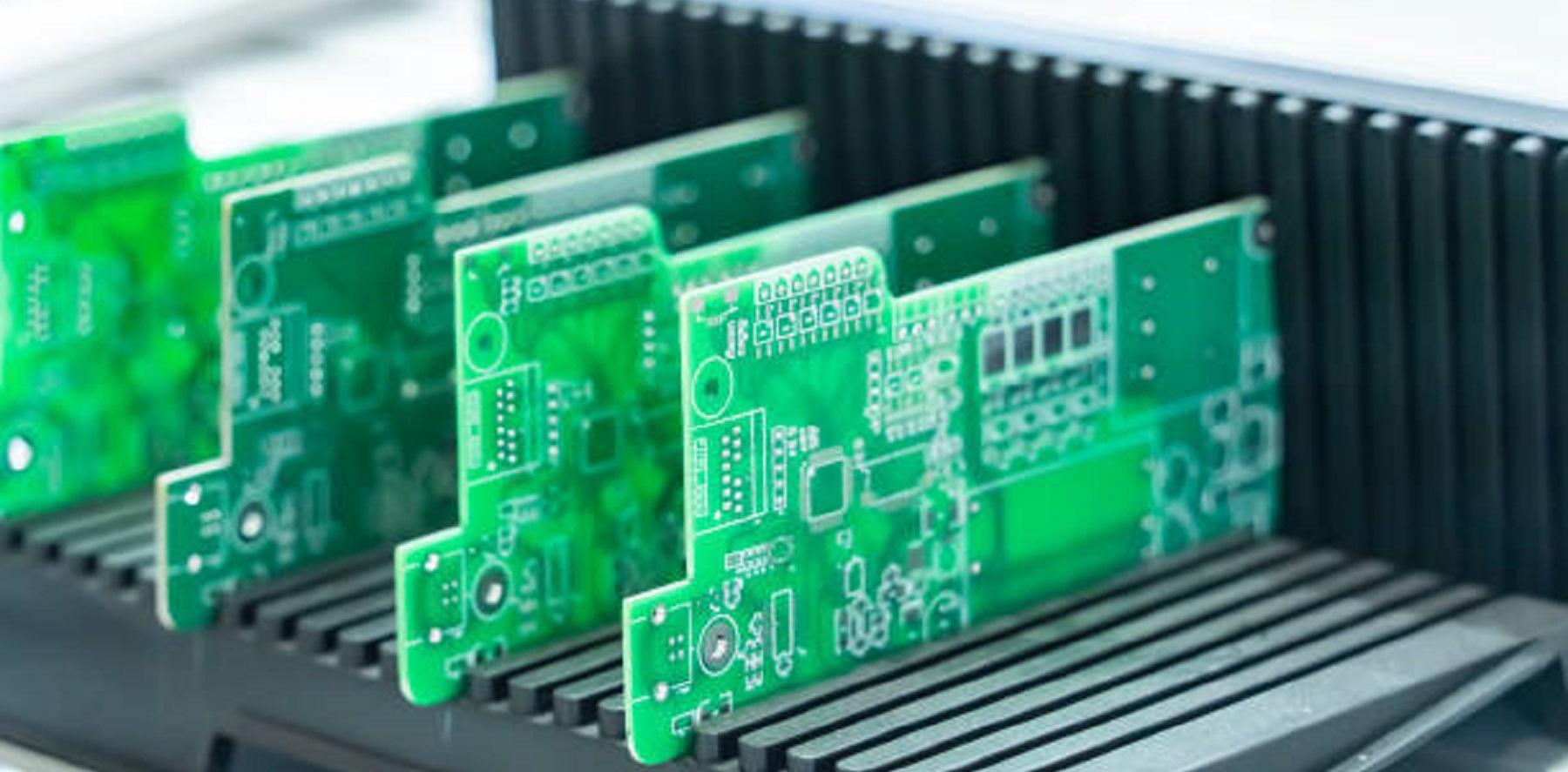
Understanding Prototype Circuit Boards
Prototype printed circuit boards or PCBs are preliminary designs of circuit boards. They are employed for testing and confirmation of new electronic devices. Prototypes are not like regular circuit boards because they are quicker and cheaper to produce since they have fewer complications and are printed. This characteristic not only saves time in production but also renders the boards dependable and secure from breakdowns through elimination of the loose or damaged wire hazards, rendering them priceless in modern electronics design.
Breadboards vs. Prototype PCBs
Solderless breadboards have been a timeless prototyping device for electronics. They allow developers to quickly prototype simple circuits by loading components in spring-loaded clips. However, breadboards are not ideal; they support only through-hole parts and lack the capability of supporting surface-mount parts. This is suboptimal because modern circuitry relies significantly on surface-mount technology because it allows one to achieve more efficient and compact designs. Thus, prototype PCBs that can support both through-hole and surface-mount parts are more flexible and realistic testing, which one needs to attain today's design requirements.
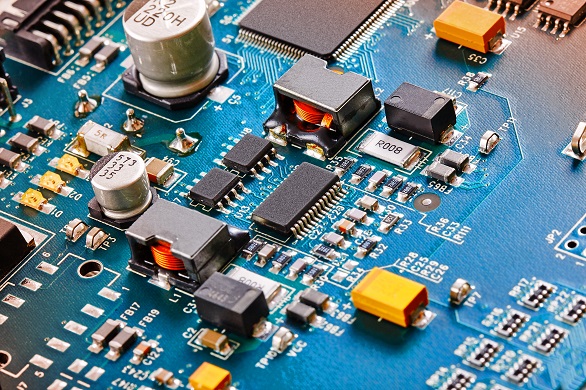
Critical Components of a Circuit Board
An intimate knowledge of the composition of a PCB is the foundation of prototype design:
Silkscreen: The topmost layer of the PCB, used to print important marks such as component names and test points, usually white.
Solder Mask: The masking layer prevents solder bridges and unintended metal contact, protecting copper traces for signal integrity.
Copper Layer: Conduits for electrical signals, thickness determining whether the board is single- or multi-layer.
FR4 Substrate: Glass-reinforced epoxy laminate that offers board stiffness and structural integrity as well as flame retardance to prevent board sagging.
PCB Prototype Building Requirements
Design Documentation
Adequate design documentation is crucial in effective prototyping. It involves:
Templates: Use templates to ensure consistency and avoid time spent on duplications.
Change Logs: Maintain rigorous change logs of revisions to record changes and justify design decisions.
Review and Sign-off: Establish a formal review process to verify correctness and completeness of documents.
Part Numbers: Revise the Bill of Materials (BOM) to reflect the evolving designs accurately.
Thoroughly documented designs eliminate errors that will convert into costly and time-consuming manufacturing issues.
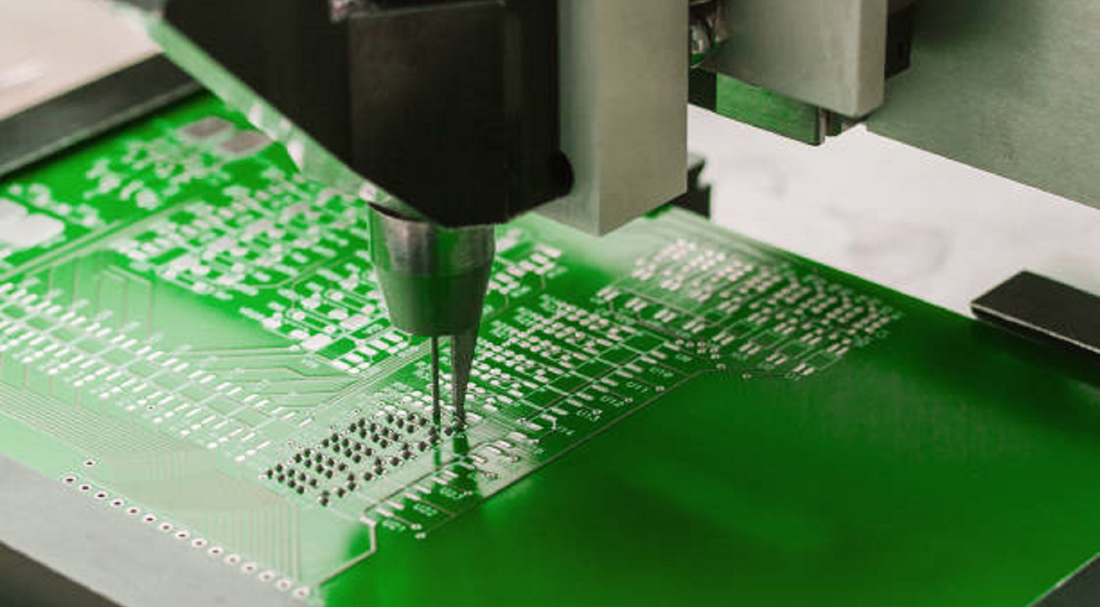
Files Required for Prototyping
Ensuring that the major files are prepared in advance facilitates a problem-free prototyping process. Major files include:
NC Drill File: Specifies locations for drilling for component leads and vias.
Centroid File: Provides the location of the components for assembly.
Gerber Files: Contain the trace layout pictures used to produce the board.
Assembly Drawings: Guides component placement on the board.
Bill of Materials (BOM): Documents components required for assembly.
ReadMe Text File: Offers further instructions or descriptions.
It is necessary to include the board outline within the drill and solder mask files to avoid fabrication errors.
Avoidance of Signal Integrity Issues
Signal integrity, RF, and electromagnetic compatibility (EMC) are critical design concerns. Correct trace routing will avoid numerous potential issues:
Cross at 90 Degrees: Traces must cross each other at 90 degrees to minimize capacitive and inductive coupling.
Avoid Parallel Traces: Parallel traces on signals cause crosstalk, which can destroy signal integrity.
Careful routing methods are essential to maintain performance, especially in radio-frequency or high-speed use.
Factors That Control Prototype Cost
Prototype cost may vary vastly based on several factors:
Material Selection: High-performance materials are expensive but may be necessary in certain applications.
Board Size: Larger boards are more expensive due to higher material usage and manufacturing complexity.
Manufacturing Speed: Fast manufacturing is more costly but can be crucial in competitive markets.
Ensuring High-Quality Prototype Services
Prior to prototype completion, strict quality control protocols guarantee reliability:
Aging Screening: Tests long-term performance to anticipate product longevity and survivability.
Functional Testing: Discovers production defects that would impact operational reliability.
Vibration Testing: Challenges component durability to mechanical stress and environmental exposure.
In-Circuit Testing: Computer-aided testing for electronic defects, testing as much as 98% of possible faults.
Prototyping is a necessary process in electronic design that fills the gap between concept and manufacture. By adhering to the specified requirements and using comprehensive design tools and methods, designers can make their circuit board prototypes as optimum as possible regarding quality and performance. Here at PCBX, we take pride in providing professional guidance and high-quality PCBs that meet all your prototype needs. Contact us today to bring your electronic designs to life with precision and reliability.
Hot Tags:

Contact us

If you can't find what you're looking for, please contact us.
Article
PCBX offers fast, high-quality turn-key PCB prototype assembly services, including fabrication, component sourcing, and testing, all at competitive prices, to accelerate product development.
 2024/08/14
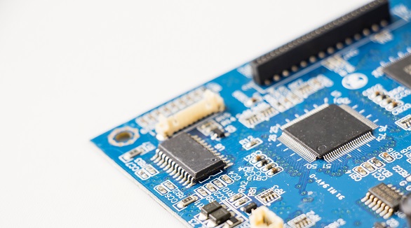
Creating PCB prototypes before full production avoids potential failures, saves costs, and ensures quality. PCBX offers rapid, accurate prototyping for efficient testing and design validation.
2024/08/06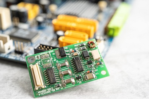
Prototyping PCBs is crucial for all designers and costs vary based on factors like board size, material, complexity, and urgency. Prices range from a few dollars to hundreds. Smaller batches cost more per unit.
2024/08/01