- Products & Capabilities

- About
- Resources
How to Check Circuit Board Components?


Circuit boards are essential for electronics but susceptible to failures; this guide details efficient diagnosis and repair techniques to ensure device reliability and safety.
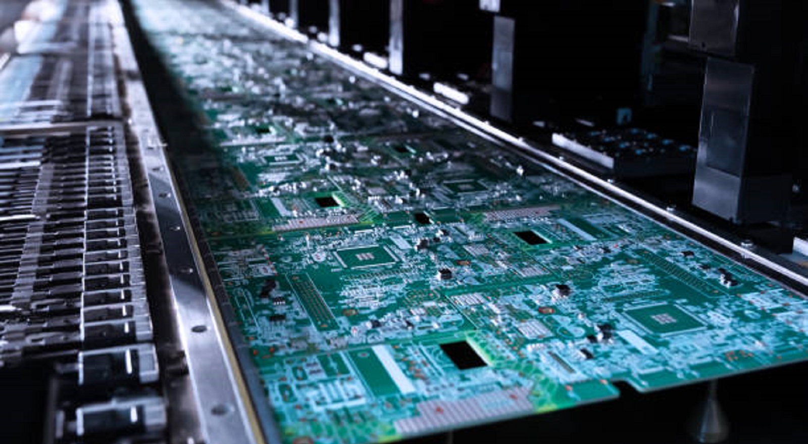
Circuit boards lie at the heart of nearly every electronic device, powering the advanced interactions that underpin our modern world. The intricate complexity of the boards, however, has the impact that when components do fail, the consequences can be vast. At PCBX, we understand the importance of testing circuit boards thoroughly to ensure reliability and safety. This article provides an in-depth guide to fault detection and diagnostic troubleshooting of components on circuit boards, keeping your equipment in prime shape.
Knowing Common Failures of Circuit Boards
One should be aware of potential failures that can occur on a circuit board before moving on to the testing and inspection:
Fluid Leakage: Usually indicates the failure of a capacitor, leading to device failure in return.
Burned Components: Resulted from excess current or overheating, affecting the functioning of the board.
Power Issues: These issues lead to an unreliable power supply, hindering performance.
Soldering Defects and Shorts: Usually resulted from improper soldering procedures, leading to connectivity defects.
Dimensional and Manufacturing Flaws: These may cause component mismatches and system functioning problems, and are a result of manufacturing flaws.
By familiarizing yourself with these common issues, you are able to conduct an improved and efficient inspection.
Initial Visual Inspection
Visual inspection is your first line of defense in finding potential circuit board issues. Here's how to perform it effectively:
Use Appropriate Tools: Use a magnifying lens or low power microscope to analyze the board surface.
Search for Physical Defects: Search for burnt tops, solder bloats, or broken components. These are signs of manufacturing or use defects.
Check Vias and Plating: Check that vias are properly plated, and check for unplated vias that were not called out. Improperly plated vias can lead to short circuits between the layers.
Identify Soldering Problems: Check for tin whiskers, solder bridges, or cracks that form unwanted connections.
Inspecting visually in detail will provide you with an instant clue and guide further testing efforts.
Using the Multimeter in Electronic Testing
A multimeter is crucial in finding electrical faults. Here's how you can use it:
Continuity Test: Check if the electrical paths have no breaks in them. It can be applied quickly to detect open circuits or discontinuities.
Resistance Measurement: Monitor resistor values to establish whether they fall within specified levels. Deviations may mean component failure or short circuits.
Capacitance Test: Essential to establish the condition of capacitors. Extensive divergence from the given values may mean a failing component.
Voltage Testing: Test input and output voltages to confirm power is being supplied correctly to the board. Power issues are typically found with erratic voltage readings.
Diode Checks: Use the multimeter to test diode function, i.e., if they are shorted or open.
Advanced Techniques for Complete Diagnosis
If simple checks and multimeter testing are insufficient, the following advanced techniques will enable deeper insight:
Infrared Imaging: Use an infrared camera to locate hotspots on the board. These can be due to overheating components or shorts, especially between internal layers.
Oscilloscope Use: Most appropriate for signal integrity validation, an oscilloscope can provide detailed waveform analysis to determine signal abnormalities.
LCR Meter: To have precise measurement of inductance, capacitance, and resistance, using an LCR meter can further your understanding of component operation.
X-ray Inspection (if required): Suitable for checking internal solder joints and connections that cannot be seen from the outside, providing a non-destructive method of inspection.
Short Circuit and Fault Fix
To effectively locate and fix short circuits, consider the following:
Measure Resistance: Check resistance between conductors and ground using the multimeter. Low levels of resistance can indicate presence of shorts.
Locate Problem Areas: Look for heavy pin areas since these are most susceptible to shorts and bridging.
Manufacturing Effects: Remember that poor fabrication practices may cause shorts. Ensure boards are subjected to Design for Manufacturing (DFM) analysis and design rule checks so that they avoid such a situation.
Identification and Handling of Busted Components
Man-handling defective components involves an orderly procedure:
Highlight Common Failure Points: Begin by checking common failure points like electrolytic capacitors, which could swell or leak when faulty.
Use Credible Sources: Compare parts with reputable databases or forums to identify typical failure modes.
Visual and Multimeter Testing: Use these tools to identify shorts that are not visible on the surface. Monitor components with unusual resistance values closely.
When Components Fail
Faulty components can be hazardous to work with. After faults have been identified, you should:
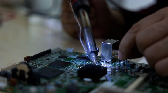
Repair or Replace: Fix defects by replacing faulty components to restore device function and safety.
Consult Experts: If necessary, consult the help of trained technicians or electricians, especially for complex fixes or for safety reasons.
Avoid Future Problems: Implement recommendations from inspection reports to improve future design and manufacturing processes, minimizing repeat defects.
Properly checking the parts of circuit boards ensures the reliability and safety of your devices. Following the step-by-step process as given in this guide enables you to diagnose and repair circuit board issues effectively. We are dedicated at PCBX to ensuring our customers the utmost device performance and reliability via thorough testing and proper fault finding. Self-repairing or repairing with professional assistance, these techniques have to be perfected in order to maintain leading-line electronic devices.
Hot Tags:

Contact us

If you can't find what you're looking for, please contact us.
Article
Soldering is vital for connecting components on PCBs in electronics, employing techniques like hand, wave, and reflow soldering to ensure reliable assemblies.
 2025/05/29
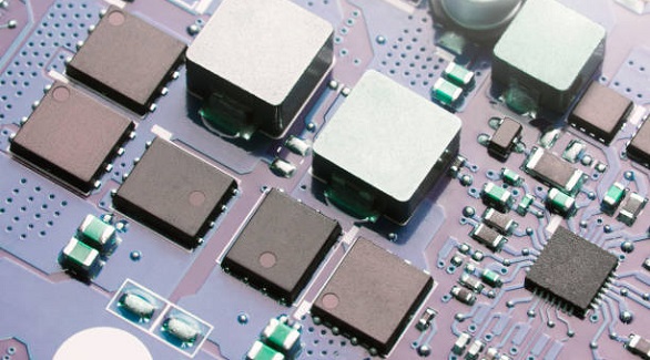
eFuses are advanced PCB fuses that reset automatically, offering fast, precise protection and versatility in electronics, enhancing device safety and reliability.
2024/11/12
Reflow soldering is vital for PCB assembly but faces challenges like solder bridging, tombstoning, and voiding. Effective solutions include optimized stencil design, thermal profiling, and precise component placement.
2024/09/25