- Products & Capabilities

- About
- Resources
Standard-Compliant Testing and Validation Workflows for Automotive ECU PCBs


Learn full ECU PCB testing & validation workflows, core automotive standards, HIL verification, reliability solutions for EV & ADAS electronics
Electronic Control Units (ECUs) are the electronic brains of all modern vehicles that control braking, powertrain, battery management (BMS) and ADAS operations. The PCB is the foundation of every ECU, which is confronted with the following harsh ambient conditions in the car: high temperature changes, high vibration, high ambient air humidity, high electric voltage changes and high electromagnetic interference (EMI). Any minor defects in PCB could lead to safety issues and expensive mass recalls. To meet the standardised global automotive requirements, manufacturers use a complete testing and validation workflow, with a full stack of standardized tests that ensure the safety, durability and performance of the PCBs.
Core Global Automotive Standards for ECU PCB Compliance
All testing protocols are based on mandatory cross-industry safety, reliability and production standards.
ISO 26262 (Functional Safety)
Steering, braking and high-voltage EV systems must meet ASIL-D requirements, which impose severe Single-Point and Latent Fault Metric (SFM) limits. It imposes the V-model development process, FMEA risk assessment and traceable test results to ensure the detection and isolation of PCB failure before system failures.
AEC-Q1 & IPC-617 (Component & Assembly Reliability)
Automotive semiconductors and passive devices are subjected to thousands of hours of thermal and humidity stress screening to qualify them for AEC-Q100/AEC-Q200 use. IPC-6012 Class 3 defines the strict temperature characteristics for Tg and anti-delamination for high reliability PCB substrates and IPC-A-610 even has soldering and BGA joint acceptance criteria, preventing vibration-induced cracking.
Environmental & Electrical Stress (ISO 16750 & ISO 7637)
Combining decades of vehicle use in the same test profiles, ISO 16750 unifies thermal cycling and vibration and humidity testing. The ISO 7637 simulates real world electrical events to test the robustness of the power circuits within a PCB, such as load dump, voltage spike and reverse battery connection.
CISPR 25 & ISO 10605 (EMC & ESD)
CISPR 25 limits EM emission to prevent radar, cam and vehicle communication bus interference. To ensure that onboard anti-static protection circuits are performing properly, a standard in the form of ISO 10605 for ESD pulse testing has been established, which specifies a value of ±25kV.
IATF 16949 (Mass Production Quality)
It's a standard that requires full batch traceability, formal PPAP procedures and standardised rework inspection to maintain PCB quality for OEM audits.

Tiered Full-Lifecycle ECU PCB Testing Workflow
Testing takes place in stages, with the aim of detecting defects early and reducing the redesign costs, which include testing of bare boards, assembled PCBs, and environmental validation.
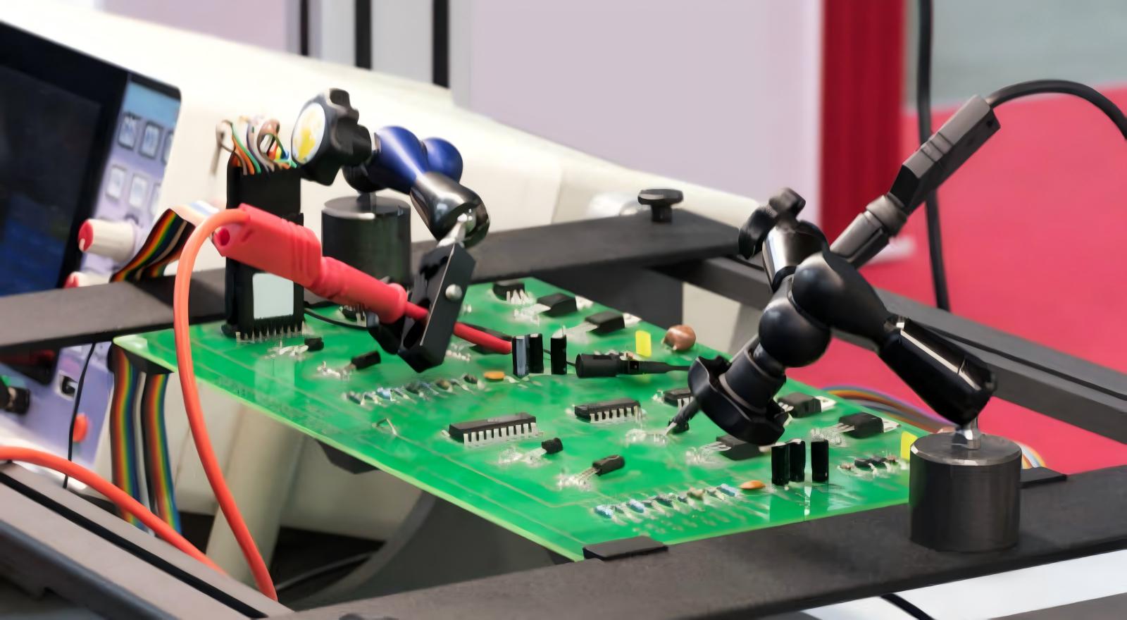
Bare Board & Assembly Pre-Screening
Bare PCBs are subjected to continuity, insulation resistance and controlled impedance testing before mounting to remove signal distortion before using CAN FD or automotive Ethernet lines. Automated Optical Inspection (AOI) quickly and efficiently locates any offset components, missing parts, and poor soldering with high resolution scanning after assembly. In-Circuit Testing (ICT) is an accurate measurement of resistor, capacitor and IC parameters using precision probes to efficiently identify hidden shorts and faulty BGA connections.
A short summary of the functional and accelerated environmental stress testing.A brief overview of the functional and accelerated environmental stress testing.
Full ECU logic and cross module communication is tested with Automated Test Equipment (ATE) which mimics real sensor signals (wheel speed, engine RPM, etc.). Burn-in testing is a process that places the PCBs under high temperatures and runs them for several hundred hours to "burn out" dormant early-life failures.
Core environmental validation is going by ISO 16750 specifications:
Thermal cycling between -40°C and 125°C to look for solder microcracks and layer delamination (500-1000 cycles);
Multi-axis vibration/mechanical shock testing of resonance effects from bumpy roads and impact loads;
Humidity corrosion tests for conformal coating and trace anti-rust test of HAST (to meet IEEE standards).
EMC, ESD and Electrical Transient Verification
To minimize PCB electromagnetic noise, engineers run radiated and conducted emission tests per the limits set by CISPR 25. ESD pulses and transient injections with high voltage can test protection circuits for static shocks and fluctuations in the power supply of the vehicle.
System-Level HIL Validation & Post-Test Failure Analysis
Hardware-in-the-Loop (HIL) testing is a must for ADAS and EV ECUs if standalone PCB testing is not enough to simulate complex real-time vehicle operating conditions. HIL platforms connect physical ECU PCBs with real-time digital vehicle simulators, with the simulated LiDAR, radar and CAN bus data passed to the physical ECU to simulate response time, multi-channel fault-tolerance and ASIL safety compliance. It allows extreme driving scenario testing without road trial safety risks that are repeatable.
The failed PCB units are subjected to Failure Analysis (FA): X-ray examination checks for internal BGA cracks, and the Cross Section Microscopy process checks for multi-layer board delamination. Test and FA data feed into design optimizations, such as reinforced copper traces, optimized ground planes and upgraded thermal layout to eliminate hotspots. All records are permanently archived in compliance with regulatory and OEM guidelines for audit.
Current Industry Challenges & Reliability Best Practices
High-voltage EV PCBs require higher standards for insulation and creepage distance testing; miniaturized HDI boards limit potential test points; high-speed automotive Ethernet sets higher standards for signal integrity; and extensive applications of ASIL-D increase fault injection test coverage.
A range of best practices industry standards help manufacturers address these challenges: Design for Testability (DFT) during PCB layout, using multi-type test equipment to ensure that all failure modes are covered, capturing real-time performance data during validation, and establishing links between the cross-functional design, testing and production teams. These have reduced development cycles, reduced long term recall risks and extended the life of the vehicle electronics to more than 15 years.
Rigorous ECU PCB testing and validation are the backbone of automotive electronic safety, ensuring adherence to globally accepted industry standards in every step of design and production. Each test procedure removes potential in-vehicle harsh operating environment risks to the hidden hardware, ranging from bare board impedance measurements to complete full system simulation on HIL. As EV and autonomous technology advances, systems for validation must continually evolve to address the challenges of high voltage, high density and high speed circuits.
Professional automotive PCB manufacturing requires comprehensive, standard-compliant testing capabilities. Specialized in automotive-grade PCB development and validation, PCBX delivers integrated one-stop ECU PCB solutions for global vehicle manufacturers. Supported by complete standardized test workflows and automotive-certified production lines, PCBX ensures every ECU PCB fully meets related requirements, stabilizing vehicle electronic performance and supporting sustainable progress across the automotive electronics sector.
Hot Tags:

Contact us

If you can't find what you're looking for, please contact us.
Article
Explore key standards, materials, application practices, and challenges of automotive PCBA conformal coatings to ensure reliability in harsh environments.
 2026/03/26
IATF 16949 is the global automotive QMS standard, building on ISO 9001 to ensure defect prevention, risk control, and high-quality PCB manufacturing.
2026/03/17
PCBs are essential in modern cars, enhancing performance, safety, and connectivity across systems like ADAS and infotainment, while facing design challenges.
2025/10/09